|
|
|
The Laboratory of Optical Studies for Advanced Materials (LOSAM) endeavors to develop and characterize frontier materials with novel optical techniques. To pursue the goal, the laboratory is equipped with (1) high-power femtosecond laser facility, (2) widely tunable picosecond coherent light sources; and (3) Yb-doped fiber laser pumped femtosecond laser with pulse shaping apparatus, etc. To probe into material properties and structures, we have developed several advanced spectroscopies and microscopies including infrared-visible sum-frequency vibrational spectroscopy (SFVS), scanning near field optical microscopy (SNOM), single-molecular detection and imaging apparatus, and 2D coherent spectroscopy (2D CS). |
The Principle of Two Dimensional Coherent SpectroscopyIn optics, phase space tomography (PST) has been employed to yield correlation functions of light fields by measuring the intensity under spatial propagation. Like the PST, quantum state tomography (QST) can recover the density matrix of conservative quantum systems under time evolution. A quantum system to be probed with 2D CS interacts with a sequence of four femtosecond and phase stable laser pulses. In the simplest version, a coherent femtosecond optical pulse is split into four parts. Three of the four beams are focused into the sample in a boxcar phase matching geometry. 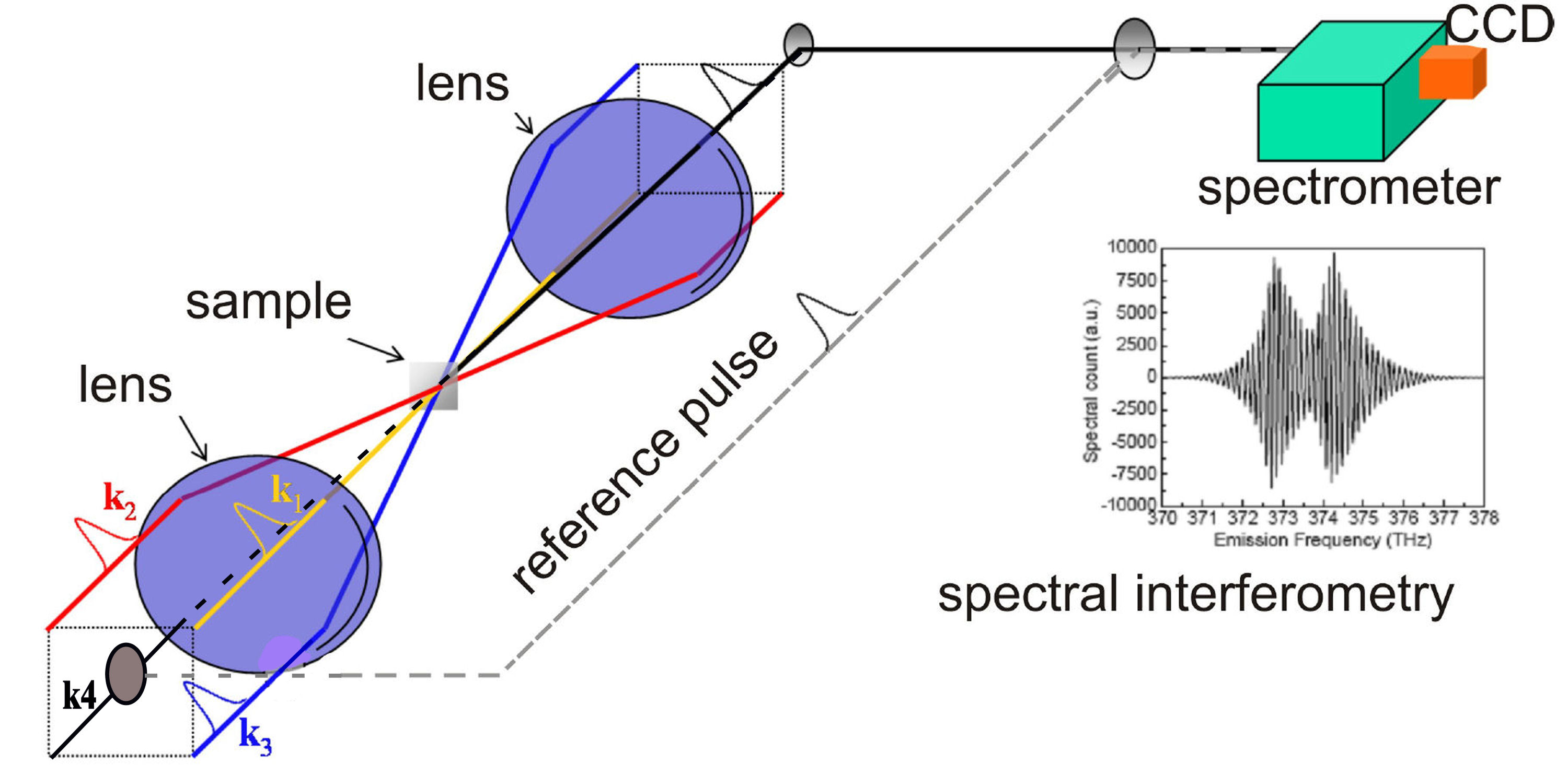
FIG. 1. Optical Setup Schematic of 2D Coherent Spectroscopy. The local oscillator pulse can be input along the echo direction (k4) or be switched out with a mirror to along a separate delay arm. A. The Principle The preparation of initial states is achieved using the first two pulses k1 and k2 arriving at times t1 and t2, which define the coherence time interval \(t = {t_1} - {t_2}\). The time interval between the second and third pulses, called the waiting time \(T = {t_3} - {t_2}\). Varying the delay T allows insight into the dissipative populations dynamics within the optical excitation manifold. Finally, at the instant t3 we can characterize the output density matrix with quantum state tomography (QST), which is usually executed by using the third pulse to selectively generate new dipole-active coherences. After the echo time \(\tau = {t_4} - {t_3}\) has elapsed, the echo signal field is emitted along the direction of \({\vec k_s} = {\vec k_2} - {\vec k_1} + {\vec k_3}\). One of the four beams k4 is attenuated by a factor of 1000 and used as a local oscillator (LO) for heterodyne detection of the echo signal. 
FIG. 2. Schematic showing the timing sequence of excitation pulses for heterodyne detection of 2D CS with a local oscillator (LO). In 2D techniques independent transitions appear solely as diagonal peaks, whereas coupled transitions can show unique cross-peaks as off-diagonal features. The 2D techniques can unfold complex and highly congested spectra by spreading them in two dimensions. 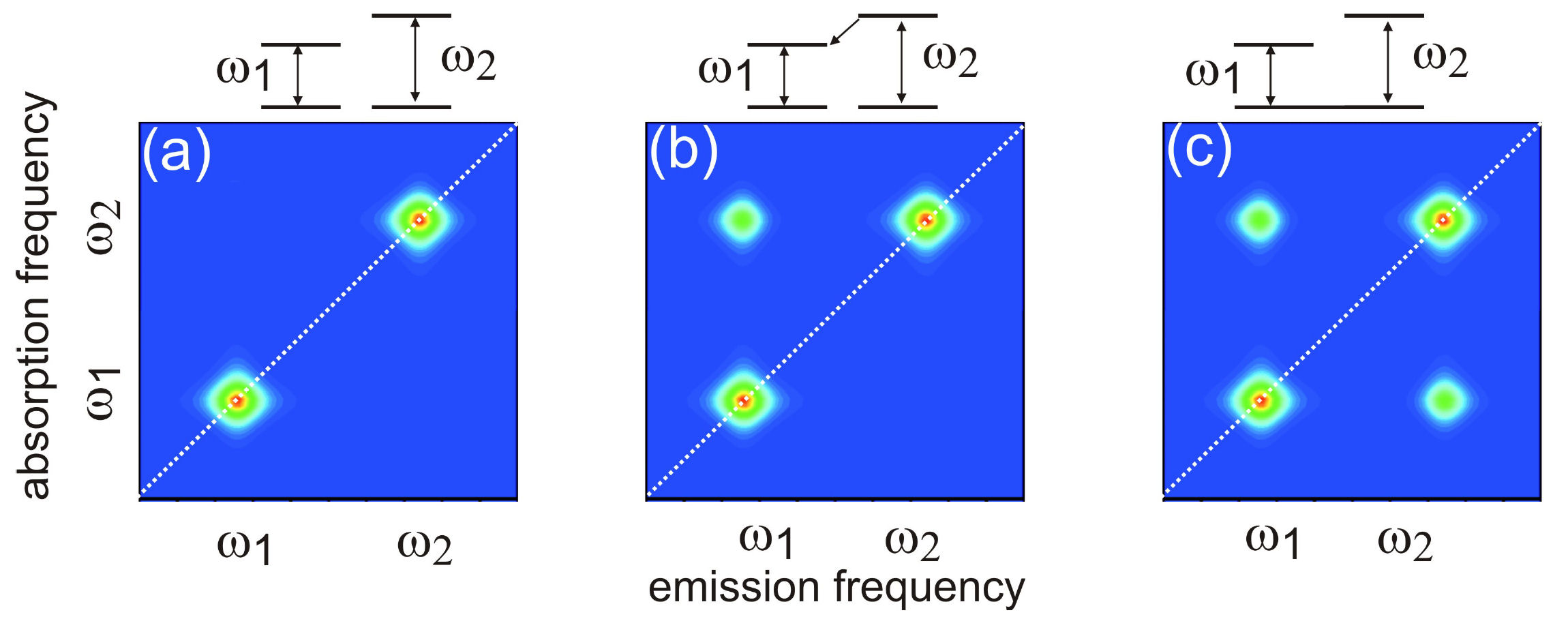
FIG. 3. Schematic diagrams illustrating the lineshapes of 2D CS as the two-level systems are mutually independent (left); coupled via excited states (center); or coupled through the ground states (right). The optical pulses-induced polarization on the molecule located at position \(\vec r \) is given by \(P(\vec r,t)\), which can be Fourier decomposed as \(P(\vec r,t) = \sum\nolimits_{{k_s}} {{P_s}(\vec r,t)\,{e^{i\,{{\vec k}_s} \cdot \vec r}}}\), where \({\vec k_s}\) are linear combinations of wavevectors of the incoming fields. Signal is produced by the radiation source i\(P(\vec r,t)\). We can choose to study a single component \({P_s}(\vec r,t)\) by detecting only the radiation moving in the direction \({{\vec{k}}_{s}}\). This is achieved by interfering the radiation with a fourth pulse moving in the same direction as \({{\vec{k}}_{s}}\). Spatial integration over the volume of probed molecules selects out the component from \(P(\vec r,t)\). The time integration yields a signal that is proportional to the components of oscillating at the frequencies of the LO, giving by \({{E}_{s}}({{\omega }_{\tau }};t,T)=\frac{2\pi l{{\omega }_{\tau }}}{c}i{{P}_{s}}({{\omega }_{\tau }};t,T)\), where l denotes the sample thickness and c the light speed in vacuum. Three dimensional coherent spectroscopy can then be achieved by performing multidimensional Fourier transform \({S_{3D}}({\omega _\tau };{\omega _T},{\omega _t}) = \int {\int {{E_s}({\omega _\tau };T,t){e^{i{\omega _t}t + i{\omega _T}T}}dt\,} dT}\). 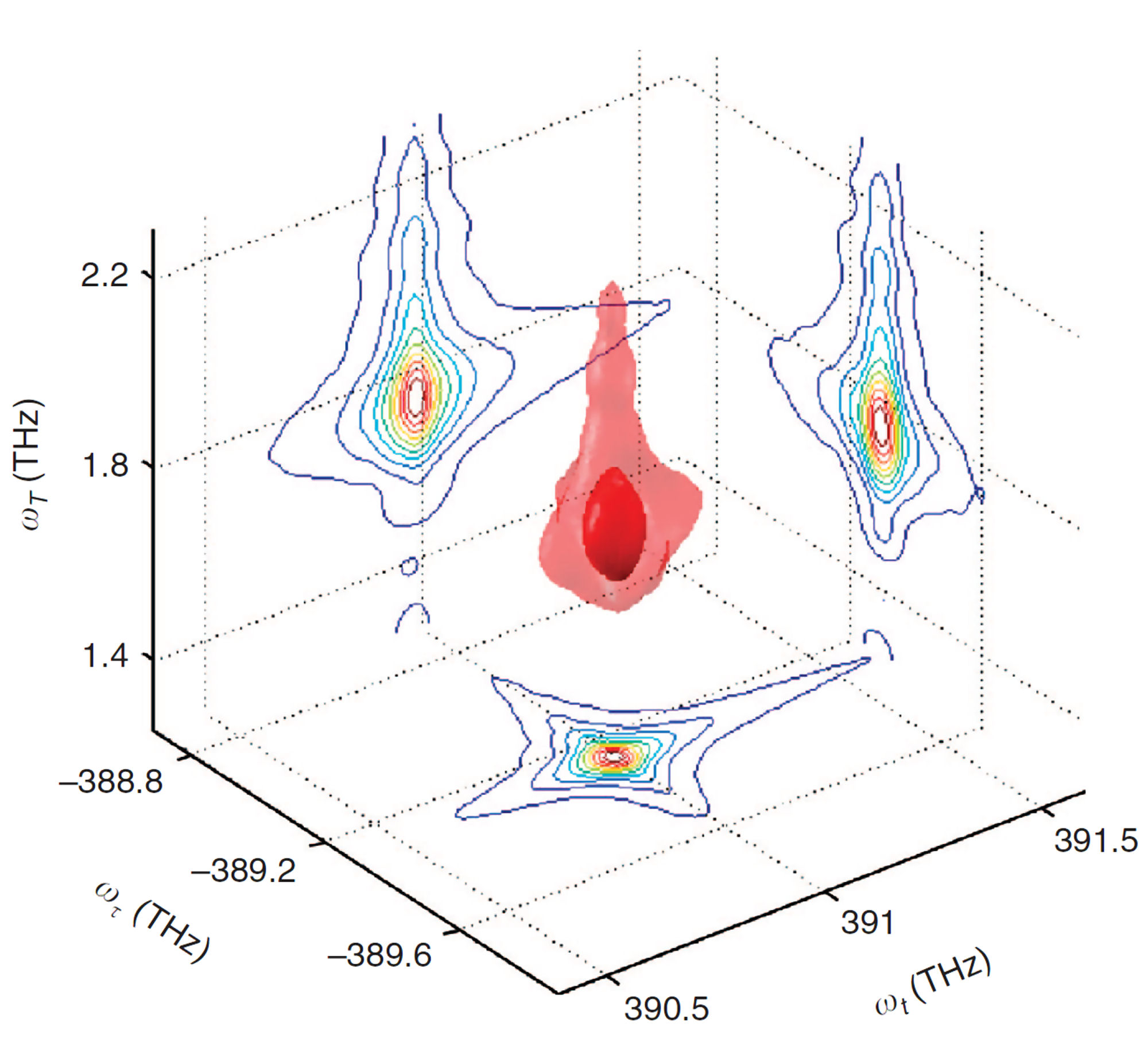
FIG. 4. Plot of \({S_{3D}}({\omega _\tau };{\omega _T},{\omega _t}) = \int {\int {{E_s}({\omega _\tau };T,t){e^{i{\omega _t}t + i{\omega _T}T}}dt\,} dT}\), which can be obtained with 3D coherent spectroscopy. Thus, the crucial step to produce a multidimensional coherent spectrum is to deduce the complex signal field \({E_s}({\omega _\tau };t,T)\). B. Spectral Interferometry for 2D CS Spectral interferometry is a widely used technique to retrieve the phase profile of an optical field. If we define the field spectrum as \({\tilde E_s}(\omega ) = \int {{E_s}(t){e^{ - i\omega t}}dt}\), referring to Fig. 2 we can express the spectrum of signal field as a sum of \({\tilde E_s}(\omega ) = {\tilde E_{echo}}(\omega ) + {\tilde E_{LO}}(\omega ){e^{ - i\omega \tau }}\). The spectrally resolved signal detected by SI reads \({I_s}(\omega ) = {\left| {{{ \tilde E}_s}(\omega )} \right|^2} = {\left| {{{\tilde E}_{echo}}(\omega )} \right|^2} + {\left| {{{\tilde E}_{LO}}(\omega )} \right|^2} + 2\left| {{{\tilde E}_{echo}}(\omega )} \right|\left| {{{\tilde E}_{LO}}(\omega )} \right|\cos [{\phi _{echo}}(\omega ) - {\phi _{LO}}(\omega ) + \omega \tau ]\). We present in Figure 5 a measured interferogram of an echo field with a local oscillator. As we scan the local oscillator from the leading side (negative \(\tau \)) to the lag side (positive \(\tau \)), the fringe spacing \(\Delta \omega \) varies inversely with \(\tau \) as \(\Delta \omega = {\textstyle{{2\pi } \over \tau }}\). For a fixed \(\tau \), the fringe spacing is distorted across the spectral profile, carrying the information of the relative phase \({\phi _{echo}}(\omega ) - {\phi _{LO}}(\omega )\). For a reference, the temporal separation between the two pulses varying from 0.1 ps to 1 ps, the SI fringe spacing \(\Delta f = {\textstyle{{\Delta \omega } \over {2\pi}}}\) changes from 10 THz to 1 THz. 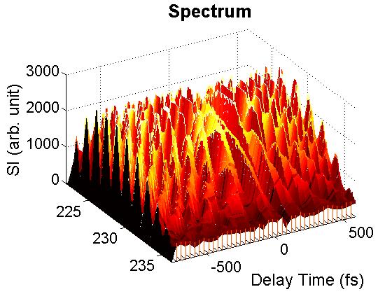
FIG. 5. Interferograms of echo field measured as the delay time of the local oscillator used was scanned from the leading (negative delay time) to the lag side (positive delay time). C. Retrieving Phase Profile with Wavelet Transform A widely used technique to determine the spectral phase difference between two light fields is to Fourier-transform the spectral interferogram from SI to a time domain. This procedure yields a function of three peaks. The AC component peaked at t = +τ is selected using a filter and then inversely Fourier-transformed to the frequency domain. A concatenation procedure is then used to recover the phase. However, if the spectral interferogram is modulated by a noise source with a frequency similar to the fringe spacing, the transform of this modulated signal will be close to the AC signal, and a temporal filter cannot exactly exclude such noise, resulting in the retrieved phase profile to be more or less dependent on the width of the temporal filter used. Furthermore, both the spectral resolution and nonlinear frequency sampling of a spectragraph can also result in phase measurement distortion. As shown by Y. Deng, et al, these drawbacks can be minimized by using wavelet transform (WT). Following to the work of Y. Deng, et al., we employed Morlet wavelet \(\begin{array}{c}W(x) = \frac{1}{{\sqrt {\pi a} }}{e^{2\pi i(x - b)/a}}{e^{ - {{(x - b)}^2}/{a^2}}}\\ = \frac{1}{{\sqrt {\pi {F_b}} }}{e^{2\pi i{F_c}x}}{e^{ - {x^2}/{F_b}}}\end{array}\) , for our WT analysis of 2D CS. The wavelet transform of an SI is defined as \(\begin{array}{c}WT({I_s};a,b) = \frac{1}{{\sqrt a }}\int {{I_s}(x){W^*}(\frac{{x - b}}{a})dx} = \frac{1}{{\sqrt {\pi a} }}\int {{I_s}(x){e^{ - 2\pi i(x - b)/a}}{e^{ - {{(x - b)}^2}/{a^2}}}dx} \\ = {\left( {\frac{{2\ln 2}}{\pi }} \right)^{1/4}}\frac{1}{{\Delta f}}\int {{I_s}(f'){e^{ - 2\pi i(f' - f)/\Delta f}}{e^{ - \ln 2{{(f' - f)}^2}/{{(\Delta f)}^2}}}df'} \end{array}\). with \(\sigma = \Delta f/\sqrt {2\pi }, \tilde b = b\,\sigma = f\), and \(\tilde a = a\sigma = \Delta f/\sqrt {\ln 2} = 1.7375 \Delta f \). A suitable value for the scaling factor is \(a = \sqrt {2\pi /\ln 2} = 3.0108 \). At the ridge of the WT modulus, \({\tilde a_{ridge}} = a/(\sqrt {2\pi } \,\tau )\), relating to a temporal separation of \(\tau [ps] = 1.7375/{\tilde a_{ridge}}(THz)\). Here a synthesized signal \(I(x) = {e^{ - {{[(x - 0.5)/0.3]}^2}}}{e^{20\pi i{{(x - 0.5)}^3}}}\cos [20 \times 2\pi x]\) with \(x\in \) [0,1] was used to illustrate the usage of WT to retrieve signal modulus and phase profile. The synthesized data is a Gaussian profile modulating on a carrier with a frequency of 20 and a phase profile distorted by a cubic dispersion. A MatLab script is available for your testing. Figure 6 presents the WT plots of the synthesized signal as functions of the scaling factors a and b. 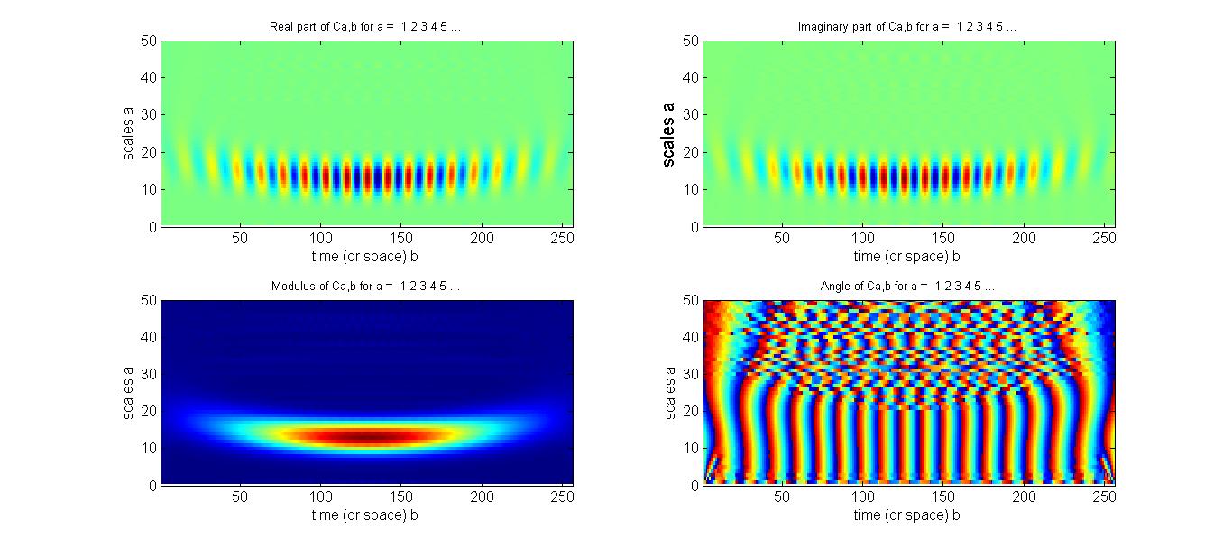
FIG. 6. WT Plots (real, imaginary, magnitude, and phase) of the synthesized signal on a functions of scaling factors a and b. As shown, the ridge of the modulus locates between 13-14. The magnitude and phase profile of the signal can be directly read out along the ridge. Figure 7 show the comparison of the retrieved profiles (blue curve and blue square symbols) with that taken from the synthesized signal (red-colored curves). The agreement is excellent as long as the scaling factor a is appropriately chosen. 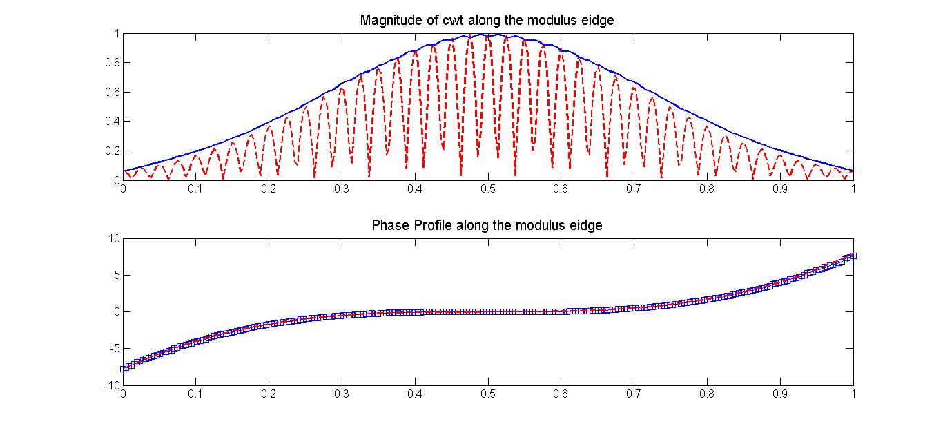
FIG. 7. Comparison of the retrieved profiles (magnitude: blue curve and phase: blue symbols) with that taken from the synthesized signal (red curves). |
Case Study 1: HeterodimerA. Model In this study, we will elaborate how to compute the 2D coherent spectrum of two nearby coupled dipolar systems, which forms a dimer, and how to analyze the time-delayed spectral interferograms to produce the 2D plot of an echo field. This formalism is also udeful for other coupled systems such as excitons in a pair of quantum wells or quantum dots. The schematic diagram of the two-level systems and the resulting coupled system is shown below. 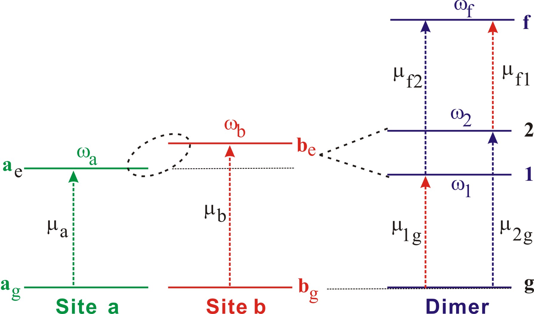
FIG. 1. Energy level diagram of two-level systems and the resulting coupled system of heterodimer. Each of the independent systems at site a and b has a ground and an excited state. The total Hamiltonian of the coupled system is then given by \(H = \hbar {\omega _a}|{a_e} > < {a_e}| + \hbar {\omega _b}|{b_e} > < {b_e}| + J({\hat \sigma _a}^ + {\hat \sigma _b}^ - + {\hat \sigma _b}^ + {\hat \sigma _a}^ - )\) with J denoting the coupling energy of the two systems. The electrons in the systems can be resonantly excited by photons with frequency near \({\omega _a}\) and \({\omega _b}\) described by the transition moment operators \({\hat \mu _a} = {\mu _a}(|{a_e} > < {a_g}| + |{a_g} > < {a_e}|)\) and \({\hat \mu _b} = {\mu _b}(|{b_e} > < {b_g}| + |{b_g} > < {b_e}|)\). Due to the coupling, the total Hamiltonian does not have a diagonal form in the site basis set. However, it can be diagonalized in the coordinate system of exciton basis \(|g>=|{{a}_{g}}>|{{b}_{g}}>,\ |1>=\cos \theta |{{a}_{e}}>|{{b}_{g}}>+\sin \theta |{{a}_{g}}>|{{b}_{e}}>,\ |2>=-\sin \theta |{{a}_{e}}>|{{b}_{g}}>+\cos \theta |{{a}_{g}}>|{{b}_{e}}>\), and \(|f>=|{{a}_{e}}>|{{b}_{e}}>\). The resulting diagonal form can be expressed as \(H = \hbar {\omega _1}|1 > < 1| + \hbar {\omega _2}|2 > < 2| + \hbar {\omega _f}|f > < f|\). Here \({\omega _{1,2}} = \omega \pm \Delta /\cos (2\theta )\) and \({\omega _f} = {\omega _1} + {\omega _2}\) with \(2\omega = {\omega _a} + {\omega _b}, 2\Delta = {\omega _b} - {\omega _a}\), and \(\tan (2\theta ) = J/(\hbar \Delta )\). In the exciton basis, the transition moment operators become \({\hat \mu } = {\mu _{1g}}|1 > < g| + {\mu _{2g}}|2 > < g| + {\mu _{f1}}|f > < 1| + {\mu _{f2}}|f > < 2| + h.c.\), where \(\left[ {\begin{array}{*{20}{c}}{{\mu _{1g}}}\\{{\mu _{2g}}}\end{array}} \right] = \left[ {\begin{array}{*{20}{c}}{\cos \theta }&{\sin \theta }\\{ - \sin \theta }&{\cos \theta }\end{array}} \right]\left[ {\begin{array}{*{20}{c}}{{\mu _a}}\\{{\mu _b}}\end{array}} \right]\) , \(\left[ {\begin{array}{*{20}{c}}{{\mu _{f1}}}\\{{\mu _{f2}}}\end{array}} \right] = \left[ {\begin{array}{*{20}{c}}{\sin \theta }&{\cos \theta }\\{ \cos \theta }&{-\sin \theta }\end{array}} \right]\left[ {\begin{array}{*{20}{c}}{{\mu _a}}\\{{\mu _b}}\end{array}} \right]\). B. Calculation of 2D Coherent Spectrum Considering a rephrasing third-order optical process, where pulse 1 arrives first with delay time \(\tau = {t_2} - {t_1} > 0\). The optical echo field radiated by the third-order polarization can be expressed as \(\begin{array}{c}{E_{echo}}(\tau ,T,t) = {E_1}^*{E_2}{E_3}\,\theta (\tau )\theta (T)\theta (t)\{ 2\mu _{1g}^4{e^{ + i{\omega _1}\tau - i{\omega _1}t}} + 2\mu _{2g}^4{e^{ + i{\omega _2}\tau - i{\omega _2}t}}\\ + \;[\mu _{2g}^2(\mu _{1g}^2 - \mu _{f2}^2) + {\mu _{1g}}{\mu _{2g}}({\mu _{1g}}{\mu _{2g}} - {\mu _{f1}}{\mu _{f2}}){e^{ + i{\omega _{21}}T}}]{e^{ + i{\omega _2}\tau - i{\omega _1}t}}\\ + \;[\mu _{1g}^2(\mu _{2g}^2 - \mu _{f1}^2) + {\mu _{1g}}{\mu _{2g}}({\mu _{1g}}{\mu _{2g}} - {\mu _{f1}}{\mu _{f2}}){e^{ - i{\omega _{21}}T}}]{e^{ + i{\omega _1}\tau - i{\omega _2}t}}\} \end{array}\). We transform \({E_{echo}}(\tau ,T,t)\) with respect to the time variables \(\tau \) and t to obtain the 2D spectrum \(\begin{array}{c}{E_{echo}}({\omega _{ex}},T,{\omega _{em}}) = \int {d\tau \,{e^{i{\omega _{ex}}\tau }}\int {dt\,{E_{echo}}(\tau ,T,t){e^{i{\omega _{em}}t}}} } \\ = E_1^*{E_2}{E_3}\,\theta (\tau )\theta (T)\theta (t)\{ 2\mu _{1g}^4\delta ({\omega _{ex}} + {\omega _1})\delta ({\omega _{em}} - {\omega _1}) + 2\mu _{2g}^4\delta ({\omega _{ex}} + {\omega _2})\delta ({\omega _{em}} - {\omega _2})\\ + [\mu _{2g}^2(\mu _{1g}^2 - \mu _{f2}^2) + {\mu _{1g}}{\mu _{2g}}({\mu _{1g}}{\mu _{2g}} - {\mu _{f1}}{\mu _{f2}}){e^{ + i{\omega _{21}}T}}]\,\delta ({\omega _{ex}} + {\omega _1})\delta ({\omega _{em}} - {\omega _2})\\ + [\mu _{1g}^2(\mu _{2g}^2 - \mu _{f1}^2) + {\mu _{1g}}{\mu _{2g}}({\mu _{1g}}{\mu _{2g}} - {\mu _{f1}}{\mu _{f2}}){e^{ - i{\omega _{21}}T}}]\,\delta ({\omega _{ex}} + {\omega _2})\delta ({\omega _{em}} - {\omega _1})\} \end{array}\). As shown, the first two terms produce the diagonal peaks of 2D spectrum, whereas the rest four terms contribute to the off-diagonal cross peaks. C. Dephasing and Population Relaxation Effects As a material driven resonantly by ultrafast optical pulses, the relaxation processes of the material must be taken into account explicitly. We can include the relaxation effects in the calculation. Assuming the spectrum of ultrashort optical pulses is much broader than the absorption band of material, the damping effect of material can be simulated with a complex frequency \({\Omega _{ij}} = ({\omega _i} - {\omega _j}) - i{\gamma _{ij}}\). Under the condition, the resulting 2D spectrum of echo field can be written as \(\begin{array}{c}{E_{echo}}({\omega _{ex}},T,{\omega _{em}}) = \int {d\tau {E_{echo}}(\tau ,T,{\omega _{em}}){e^{i{\omega _{ex}}\tau }}} \\ = E_1^*{E_2}{E_3}\,\theta (T)\,\{ \;\mu _{1g}^4{e^{ - i{\Omega _{11}}T}}G({\omega _{ex}} + \Omega _{1g}^*)G({\omega _{em}} - {\Omega _{1g}}) + \mu _{2g}^4{e^{ - i{\Omega _{22}}T}}G({\omega _{ex}} + \Omega _{2g}^*)G({\omega _{em}} - {\Omega _{2g}})\\ - {\mu _{1g}}{\mu _{f1}}({\mu _{1g}}{\mu _{f1}}{e^{ - i{\Omega _{11}}T}} + {\mu _{2g}}{\mu _{f2}}{e^{ - i{\Omega _{21}}T}})G({\omega _{ex}} + \Omega _{1g}^*)G({\omega _{em}} - {\Omega _{f1}})\\ - {\mu _{2g}}{\mu _{f2}}({\mu _{2g}}{\mu _{f2}}{e^{ - i{\Omega _{22}}T}} + {\mu _{1g}}{\mu _{f1}}{e^{ + i{\Omega _{21}}T}})G({\omega _{ex}} + \Omega _{2g}^*)G({\omega _{em}} - {\Omega _{f2}})\\ + \mu _{1g}^2\mu _{2g}^2{e^{ - i{\Omega _{21}}T}}G({\omega _{ex}} + \Omega _{1g}^*)G({\omega _{em}} - {\Omega _{2g}}) + \mu _{1g}^2\mu _{2g}^2{e^{i{\Omega _{21}}^*T}}G({\omega _{ex}} + \Omega _{2g}^*)G({\omega _{em}} - {\Omega _{1g}})\;\} \end{array}\) , where \(G({\omega _{ex}} + \Omega _{1g}^*) = 1/[({\omega _{ex}} - {\omega _1}) + i{\gamma _{1g}}]\) and \(G({\omega _{em}} + \Omega _{1g}) = 1/[({\omega _{em}} - {\omega _1}) + i{\gamma _{1g}}]\). By using \({\omega _a}\)=226 THz, \({\mu _a}\)=0.8 D, \({\omega _b}\)=232 THz, \({\mu _b}\)=1.6 D, J =3 THz, and \({\gamma _{ij}}\)=3 THz, we can synthesize \({E_{echo}}({\omega _{ex}},T,{\omega _{em}})\) and the result of \(\left| {{E_{echo}}({\omega _{ex}},T = 0,{\omega _{em}})} \right|\) was presented in the 2D plot. The unequal off-diagonal peaks at \(({\omega _{em}},\, - {\omega _{ex}})\) = (233, -225) and (225, -233) imply that the coupling is asymmetric with the contributions from the third and fifth terms (in red) being in the same phase, whereas those from the fourth and sixth (in blue) are out of phase. 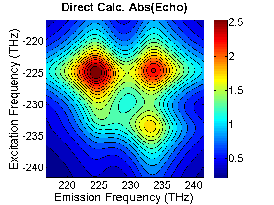
FIG. 2. Spectral interferograms of echo signal field emitted from. D. Heterodyne Measurement of Spectral Interferogram Researchers typically used heterodyne detection methodology to retrieve \({E_{echo}}(\tau ,T,t)\) from spectral interferogram. In this method, \({E_{echo}}(\tau ,T,t)\) is mixed with an optical field \({E_{LO}}(t - {t_w})\) with a temporal separation t_w, which yields a total field \({E_{tot}}(t) = {E_{echo}}(\tau ,T,t) + {E_{LO}}(t - {t_w})\) at the focal plane of an area detector attached to a spectrograph. The generated spectral interferogram (SI) can then be described by \(S(\tau ,T,\omega = {\omega _{em}}) = {\left| {{E_{LO}}(\omega )} \right|^2} + {\left| {{E_{echo}}(\tau ,T,\omega )} \right|^2} + 2\left| {{E_{LO}}(\omega )} \right|\left| {{E_{echo}}(\tau ,T,\omega )} \right|\cos [{\phi _{echo}}(\omega ) - {\phi _{LO}}(\omega ) - \omega {t_w}]\). By using the formula, we synthesized the time-delayed SI emitted from the dimer. The SI at T=0 and \({t_w}\)=1 ps is shown below. 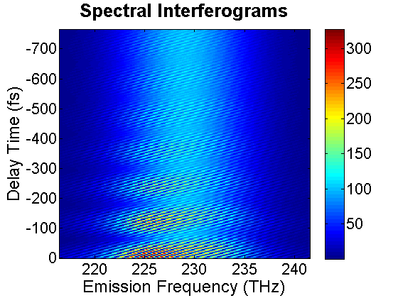
FIG. 3. Time-delayed spectral interferograms of photon echo emitted by a dimer. As illustrated in the above section, wavelet transform is effective to retrieve the phase and thereby the complete optical field information can be deduced from the measured SI. To verify the accuracy of the methodology, we implemented wavelet transform in our 2DCS data analysis script. Using the synthesized SI of the heterodimer model as input data, we successfully recovered the echo field \({E_{echo}}(\tau ,T,{\omega _{em}})\). The magnitude of the field is presented in the following. 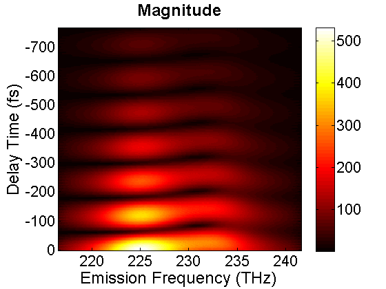
FIG. 4. Magnitude of the time-delayed echo field emitted from a dimer. Our data analysis script also produces the real and the magnitude of the 2D CS plot. The magnitude of the 2D CS plot is shown on the left diagram. The off-diagonal cross peaks are asymmetric, indicating that the coupling between two excited levels of the coupled system is asymmetric. For comparison, we also direct Fourier transform the time-delayed echo field \({E_{echo}}(\tau ,T,{\omega _{em}})\). \(\begin{array}{c}{E_{echo}}({\omega _{ex}},T,{\omega _{em}}) = \int {d\tau {E_{echo}}(\tau ,T,{\omega _{em}}){e^{i{\omega _{ex}}\tau }}} \\ = E_1^*{E_2}{E_3}\theta (T)\int {\{ \;\mu _{1g}^4{e^{ - i{\Omega _{11}}T}}{e^{i({\omega _{ex}} + \Omega _{1g}^*)\tau }}G({\omega _{em}} - {\Omega _{1g}}) + \mu _{2g}^4{e^{ - i{\Omega _{22}}T}}{e^{i({\omega _{ex}} + \Omega _{2g}^*)\tau }}G({\omega _{em}} - {\Omega _{2g}})} \\ - {\mu _{1g}}{\mu _{f1}}({\mu _{1g}}{\mu _{f1}}{e^{ - i{\Omega _{11}}T}} + {\mu _{2g}}{\mu _{f2}}{e^{ - i{\Omega _{21}}T}}){e^{i({\omega _{ex}} + \Omega _{1g}^*)\tau }}G({\omega _{em}} - {\Omega _{f1}})\\ - {\mu _{2g}}{\mu _{f2}}({\mu _{2g}}{\mu _{f2}}{e^{ - i{\Omega _{22}}T}} + {\mu _{1g}}{\mu _{f1}}{e^{ + i{\Omega _{21}}T}}){e^{i({\omega _{ex}} + \Omega _{2g}^*)\tau }}G({\omega _{em}} - {\Omega _{f2}})\\ + \mu _{1g}^2\mu _{2g}^2{e^{ - i{\Omega _{21}}T}}{e^{i({\omega _{ex}} + \Omega _{1g}^*)\tau }}G({\omega _{em}} - {\Omega _{2g}}) + \mu _{1g}^2\mu _{2g}^2{e^{i{\Omega _{21}}^*T}}{e^{i({\omega _{ex}} + \Omega _{2g}^*)\tau }}G({\omega _{em}} - {\Omega _{1g}})\;\} d\tau \end{array}\). to produce the 2D plot, which is presented on the right-hand side. The similarity of the two plots thus verifies the accuracy of this data analysis methodology. 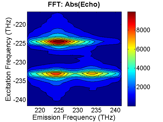 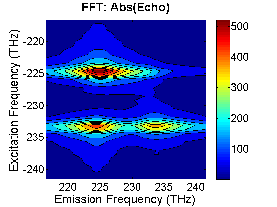
FIG. 5. (Left) 2D plot of the echo field emitted from a dimer calculated by direct Fourier transform the time-delayed echo field. (right) 2D plot was calculated by retrieving the echo field from SI and then Fourier transform the field to produce the plot. |
Case Study 2A. Title to be posted. |
Case Study 3A. Title to be posted. |